How Solenoid Valve Works
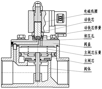
Solenoid valve is an industrial equipment controlled by electromagnetic, and it is an automatic basic component used to control fluid. It belongs to actuator and is not limited to hydraulic and pneumatic. Used in industrial control systems to adjust the direction, flow, speed and other parameters of the medium. The solenoid valve can be matched with different circuits to achieve the desired control, and the control accuracy and flexibility can be guaranteed. There are many kinds of solenoid valves, and different solenoid valves play a role in different positions of the control system
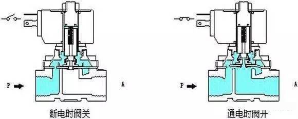
Working principle diagram of solenoid valve
1. Direct acting solenoid valve
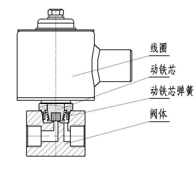
Direct acting solenoid valve structure diagram (Figure 1)
The working principle of the direct-acting solenoid valve: when the power is turned on, the solenoid coil generates an electromagnetic force to lift the closing member from the valve seat, and the valve opens; when the power is off, the electromagnetic force disappears, the spring presses the closing member on the valve seat, and the valve closes.
Features: It can work normally in vacuum, negative pressure and zero pressure, but the diameter generally does not exceed 25mm.
2. Step-by-step direct-acting solenoid valve
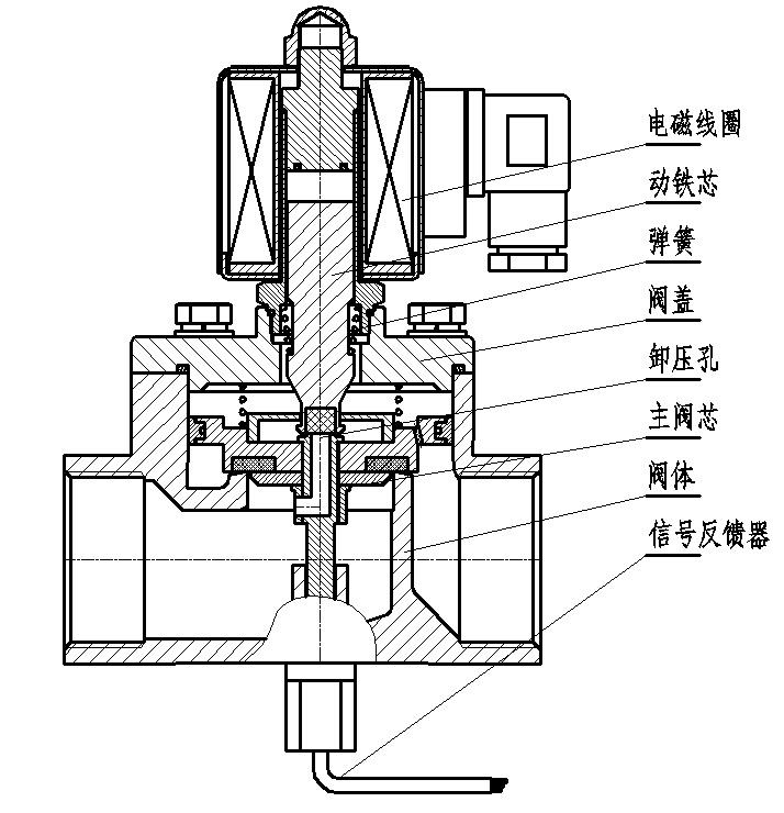
Step-by-step direct-acting solenoid valve structure diagram (Figure 2)
The working principle of the step-by-step direct-acting solenoid valve: it is a combination of direct-acting and pilot-operated. When there is no pressure difference between the inlet and the outlet, after the power is turned on, the electromagnetic force directly pushes the pilot valve and the main valve closing part upward in turn. Lift, the valve opens. When the inlet and outlet reach the starting pressure difference, after the power is turned on, the electromagnetic force pilots the small valve, the pressure in the lower chamber of the main valve rises, and the pressure in the upper chamber drops, so as to use the pressure difference to push the main valve upwards; when the power is off, the pilot valve uses a spring The force or medium pressure pushes the closing member, moving downward, causing the valve to close.
Features: It can also act safely under zero pressure difference or vacuum and high pressure, but the power is large and must be installed horizontally.
3. Pilot solenoid valve
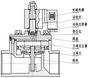
Structural diagram of pilot solenoid valve (Fig. 3)
The working principle of the pilot solenoid valve: when the power is turned on, the electromagnetic force opens the pilot hole, the pressure of the upper chamber drops rapidly, and a pressure difference between the upper and lower parts is formed around the closing part, and the fluid pressure pushes the closing part to move upward, and the valve opens; when the power is off , the spring force closes the pilot hole, the inlet pressure through the bypass hole quickly forms a pressure difference around the valve closing member, and the fluid pressure pushes the closing member to move down to close the valve.
Features: The upper limit of the fluid pressure range is high, which can be installed arbitrarily (need to be customized) but must meet the fluid pressure differential conditions.
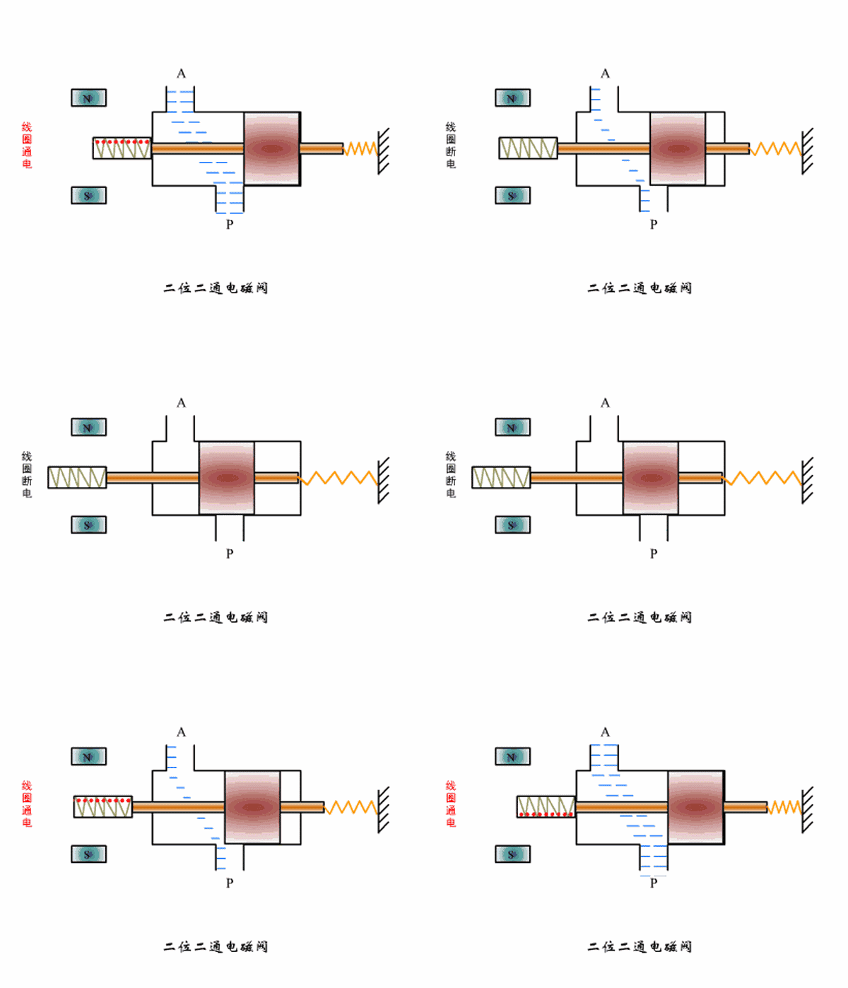
Two-position two-way solenoid valve working principle diagram
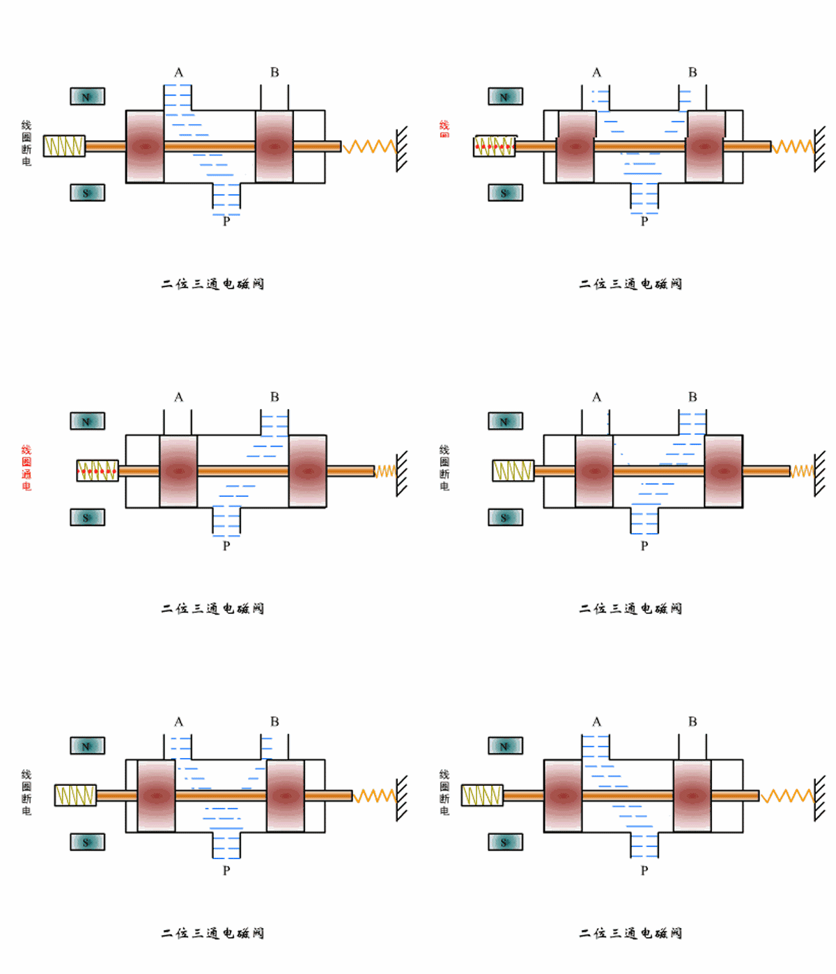
Working principle diagram of two-position three-way solenoid valve
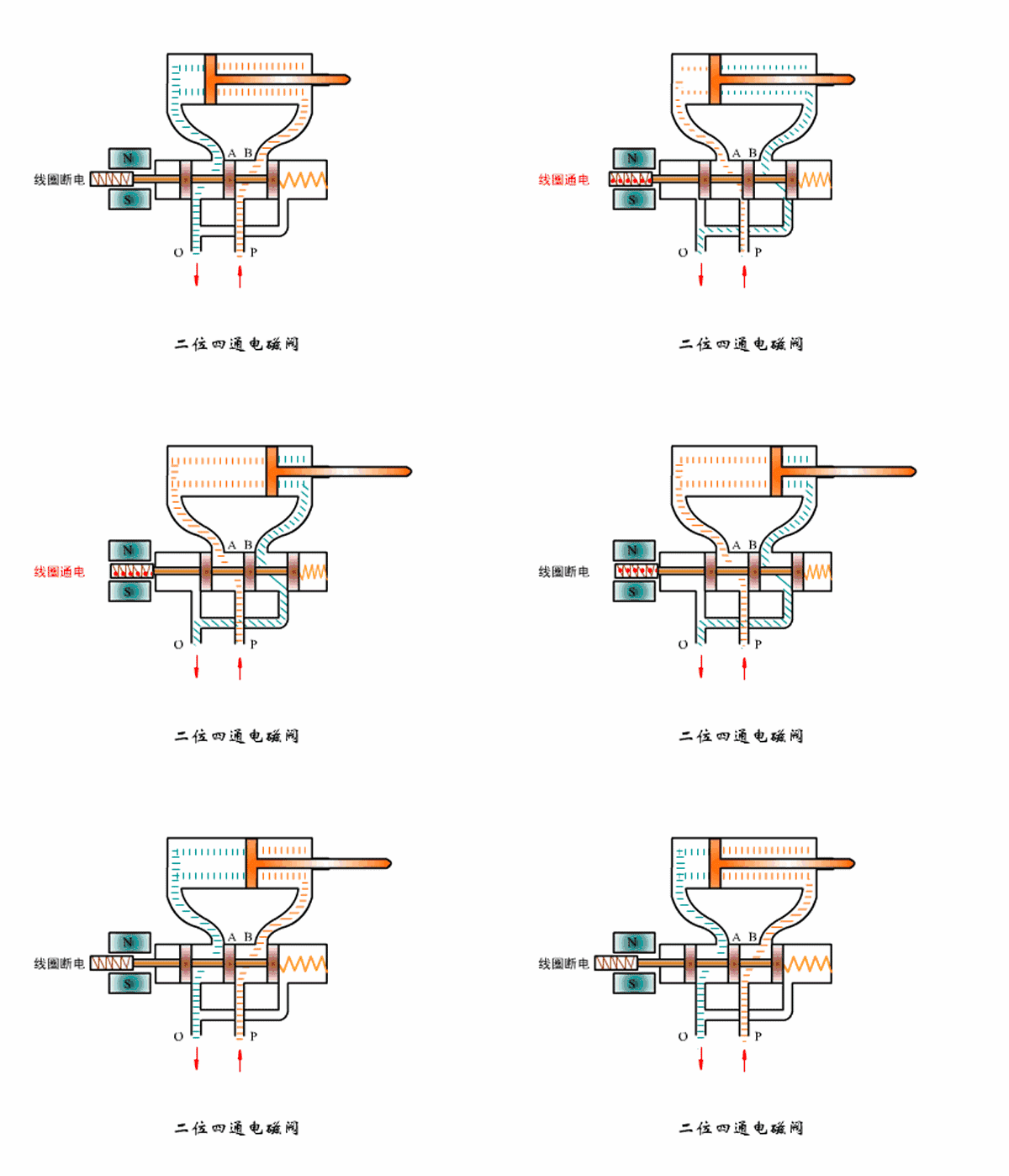
Working principle diagram of two-position four-way solenoid valve
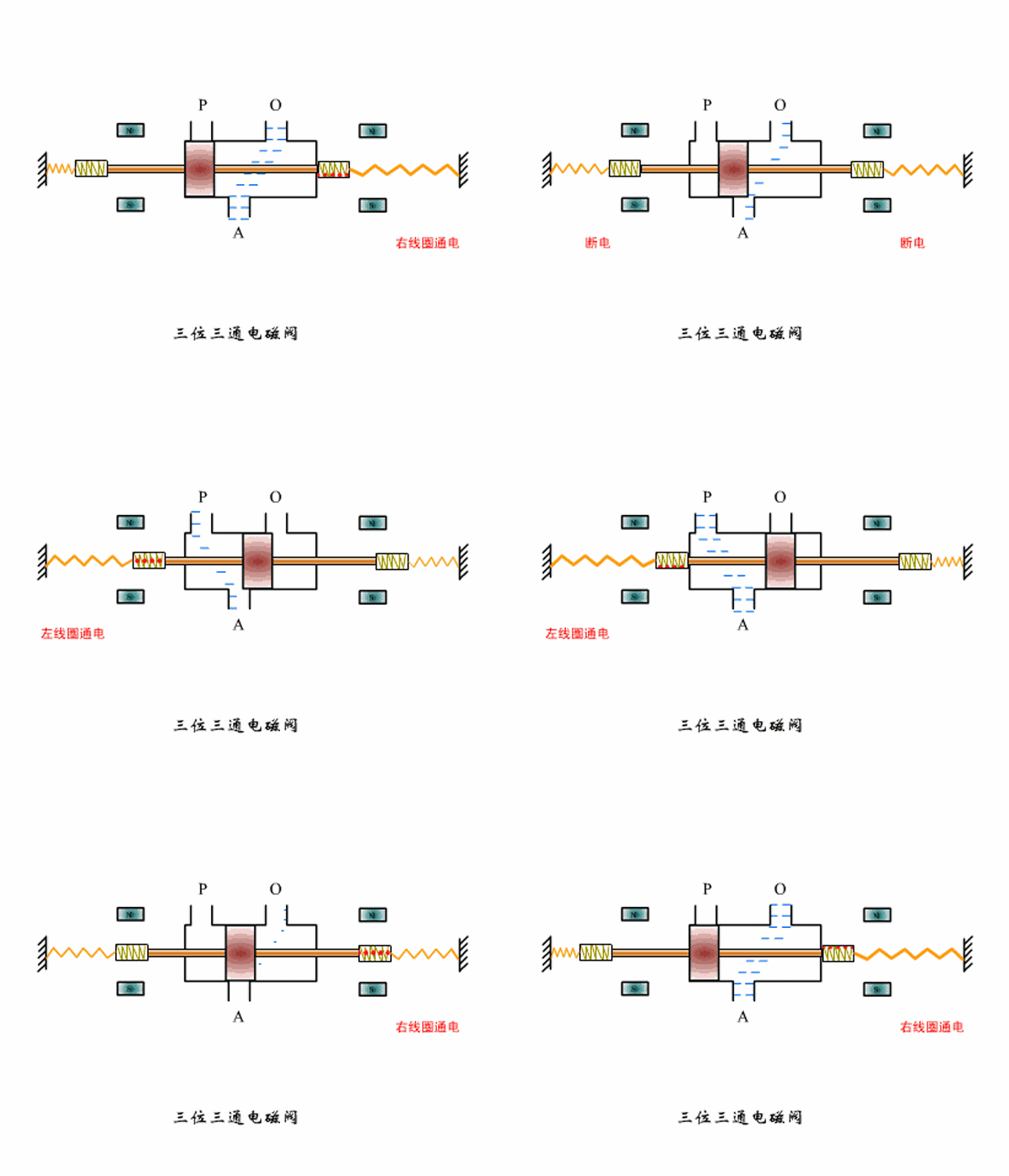
Three-position three-way solenoid valve working principle diagram
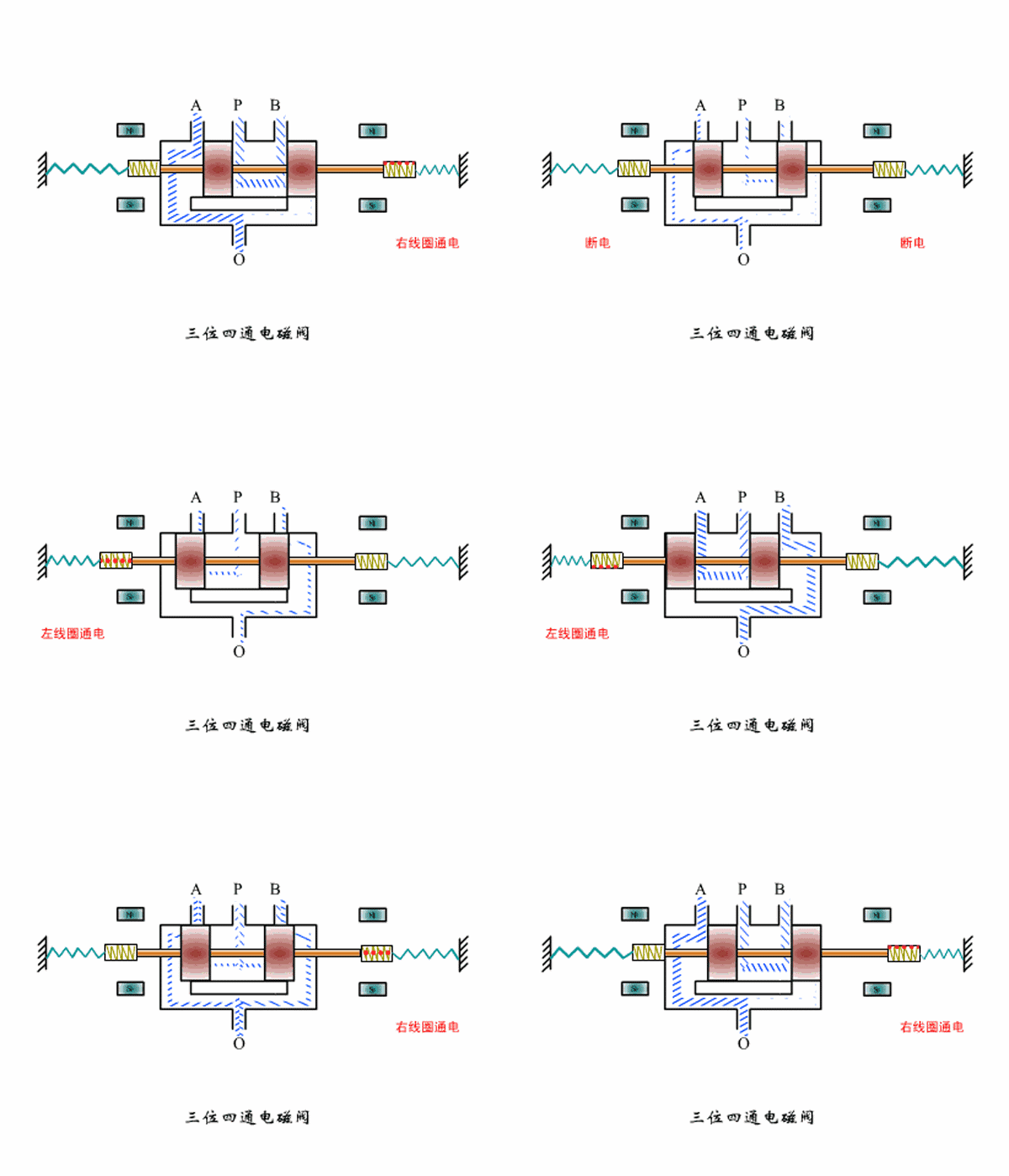
Three-position four-way solenoid valve working principle diagram